News
Inductance basics 2-inductance unit, voltage and current relationship, time constant and impedance (interpretation of textbook formula)
- Author:Roger
- Release on:2021-01-13
The last article is about ‘perceptual’ to understand inductance, and this article is about ‘rational’ to understand inductance. We will list some textbook formulas, while adhering to the tradition of this column, put some vivid gif animations to help understand.
1. The unit of inductance
As can be seen from the previous article, inductance reflects the ability of a device to resist current changes. This "confrontation" is reflected in the induced current and induced electromotive force (also called: Back EMF) on the inductor.
The unit of inductance is Henry, and the symbol is L. The definition of L=1 Henry is: the current changes at a rhythm of 1 ampere per second (1A/s). If the voltage of the induced electromotive force generated on the inductor is 1V, this inductance is 1 Henry.
In radio and communication equipment, the common inductance unit is nH (nanohenry), which can deal with MHz-level current changes; in power supplies and power supply equipment, the common inductance unit is μH (uH, microhenry), which copes with KHz-level current Change; In audio equipment, the common inductance unit is mH (haoheng), which can deal with current changes of hundreds of Hz to 2KHz.
In the process of resisting current changes, the inductor is accompanied by the conversion of electrical and magnetic energy. The larger the capacity of the inductor, the greater the energy that can be converted and stored.
2. Voltage and current changes on the inductor
Let’s take a look at the relationship between the voltage and current on the inductor: V=-L*di/dt
This formula reflects that the voltage of the induced electromotive force on the inductor is related to the speed of the current change.
In the case of a constant L, the faster the current changes, the higher the induced electromotive force voltage generated. Especially when the circuit switch is opened or closed, the instantaneous change of the current can cause sparks to appear at the place of the circuit switch (the spark can be generated only when the air is broken down. The voltage is at least tens of thousands of volts. The instantaneous voltage is very high. Short, but not necessarily large in energy).
We build a circuit composed of inductance, resistance, and power (periodic square wave), as shown below:
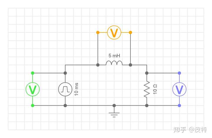
A voltmeter is connected in parallel to each device for easy viewing of the waveform. In particular, through the voltage across the resistor, the current across the circuit can be estimated (Ohm's law). The power supply is a periodic square wave of Max 10V, Min 0V, and 100Hz.
Let's take a look at the voltage and current waveform changes on the inductor:
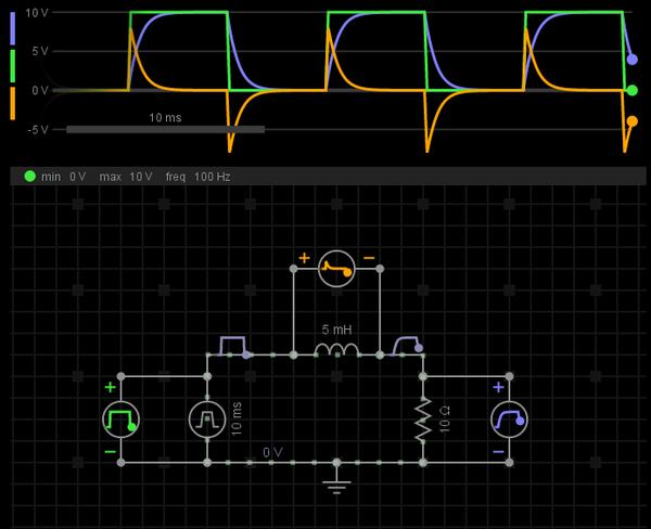
Among them, the green waveform represents the power supply voltage change; the yellow waveform represents the inductor voltage change; the blue waveform represents the resistance voltage change, which also reflects the current change on the entire circuit.
When the power supply changes from 0V->10V, the voltage of the inductor generates a positive pulse (voltage sudden change), the polarity of this pulse is opposite to the polarity of the power supply voltage. Because the inductor voltage weakens the influence of the power supply voltage, the current does not suddenly increase. The current of the entire circuit starts from 0A and gradually rises (the current cannot change suddenly) until it reaches a steady state.
When the power supply changes from 10V->0V, the voltage of the inductor generates a negative pulse (voltage sudden change), the polarity of this pulse is the same as the polarity of the power supply voltage. Since the inductor voltage continues the influence of the power supply voltage, the current does not suddenly decrease. The current of the entire circuit starts from 1A (10V/10Ω) and gradually decreases (the current cannot change suddenly) until it reaches a steady state.
This is consistent with what we said in the previous article that inductance is an inertial device in the field of electromagnetics. It does not like the current to change and always uses its own energy to maintain the original state of the current.
Note that there are no switching devices deliberately placed in this circuit, even when the power supply voltage is at least 0V, the entire circuit is turned on. But if you put a switch in the circuit, the situation when the switch is off is different from the situation when the power supply is 0V, we will analyze it later. You can imagine that the inductor acts as an inertial device of current. If the circuit is suddenly disconnected and the current has no loop, what will happen?
Third, the time constant of the inductance
In the LR circuit, in response to external excitation (DC) changes, it takes a certain process for the voltage and current of the inductor to reach a stable state, and its waveform conforms to the exponential change:
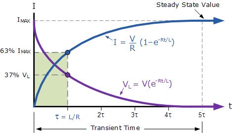
The time constant τ=L/R. After 5 τ, the voltage and current of the inductor tend to be stable, especially for DC, at this time the inductor is equivalent to a short circuit, and the current reaches the maximum Imax=V/R.
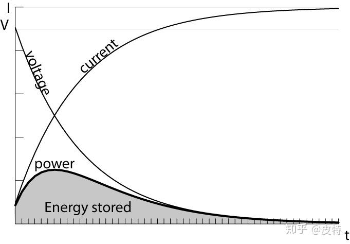
In the process of reaching a steady state, the inductor is also storing energy (converting electrical energy into magnetic energy, corresponding to the above-mentioned excitation power change from 0V->10V) or releasing energy (converting magnetic energy into electrical energy, corresponding to the aforementioned excitation power from 10V- >0V changes). So this constant is also called the charge and discharge time constant.
Fourth, the impedance of the inductor-inductive reactance
Like capacitance, impedance is needed to measure the performance of inductance under different frequency excitation. In particular, for pure inductive circuits, impedance is inductive reactance.
The formula for calculating inductance and inductance is X=2π*f*L. The higher the frequency, the greater the inductive reactance.
For example, if we increase the power supply excitation in Figure 2 from 100Hz to 1KHz, what will happen?
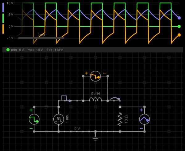
In this circuit, as the frequency increases, it means that the impedance of the inductor becomes larger, so more voltage can be distributed to the inductor, and less voltage is distributed to the resistor. From another perspective, if the resistor is the load, isn't it a step-down circuit?
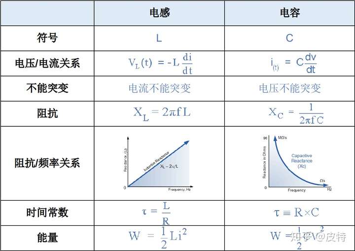
5. Comparison of inductance and capacitance (formula)
Let's list the comparison of inductance and capacitance to help you remember:
(At the end of the full text, the formula in the textbook is really important)