News
74LS175 working principle and circuit diagram
- Author:ROGER
- Release on:2021-07-20
There should be some small partners not not understand 74LS175, then what is the 74LS175?The following small series brings you the working principle of 74LS175 andCircuitFig.
74LS175 working principle and circuit diagram
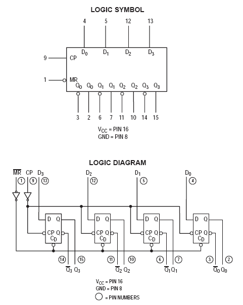
74LS175 is 4DtriggerThere is a total of 6 sets of D triggers in which there are 6 sets of D triggers, which can constitute a functional component such as registers, atron.When 1 foot is 0, all Q output is 0, Q Non output is 1; 9 foot positionclockInput, 9 foot rises along the level of the corresponding flip-flop D into the D trigger.
After the circuit is powered, press the reset button S, 1Q, Q2, Q, Q4 output high.The circuit will enter the preparation status.
The circuit diagram of 74LS175 is as follows:
The 74LS175 pins are as follows: